I decided to forge ahead and cross the Rubicon, that is modifying the Black Water (as dirty as the Black Water Iraq war badass covert contractor) level indicator panel and repurpose it for the refrigerator control panel. As it turns out there are many constraints on where I can cut the opening for the Ink Bird. There are the existing graphics that I want to obscure and preserve. I have to comprehend the cabinet opening which turns out to be not symmetrical WRT to the faceplate. It is offset to one long side.
Failure to comprehend all these constraints will make for an ugly hack job, so I took my time measuring twice and cut once.
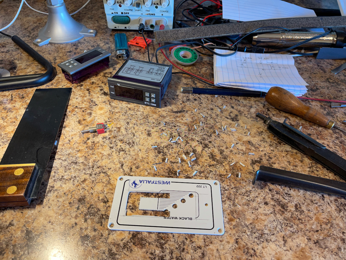
see the mounting holes are offset more to one long edge
it was so long ago that I forgot that the black water level sensor also serves as the conduit for what I remember of 12Vdc supplying the cabin lights of this overhead cabinet; by unplugging and decommissioning the level indicator board you will lose the lighting unless something is done to restore it
I'd like to preserve the rocker switch but it is not possible to house the Ink Bird as well as it as there isn't enough real estate unless the cabinet opening is enlarged carefully
I use this vintage nibbler and it still took a lot of time
full frontal view - looked like Westfalia intended it 😆
a test fit and all is well
next I remove the relay for the heating function so it would not come on invertently and waste energy
the model number legend on the no name Ink Bird equivalent is crooked so I swapped in faceplate from the bad Ink Bird unit
I am not about to tackle hacking in the display enable switch as that takes a lot of time and finding the CMOS quad 2-1 multiplexer to wire onto the board. In fact this controller, not having both display for F and C, and the RH% build option display, likely only needs three or may be even two of the 2-1 multiplexer. If so a DPST or DPDT small toggle switch would be easier.
A couple of finer discoveries. The relays in the Ink Bird are 12V despite the MCU and all the circuit are 5Vdc. This means the coils are driven by open drain drivers of the MCU. The relay consumes about 30mA to switch on.
the 12V relay coil consumes 30mA
I now believe the Danfoss CPT module likely has either a reed relay, or even semiconductor switching transistors, which should consume much less current than this low power relay. I can hack out the Ink Bird cooling relay also and just use the open drain driver to drive the Danfoss CPT module. However I may actually need open source, so that is a no go unless I hack in a simple transistor to invert it. The hack is getting complicated. Complexity is best avoided unless the benefit outweighs.


No comments:
Post a Comment