My no thrill electronics toys from China have been arriving faster than I have time to digest let alone putting them to use. I have been wanting to play with this Ink Bird temperature controller since its initial debut many years ago. I purchase the ITC-1000F version as it has 110Vac power supply rather than the original 12V. I want to use it to replace the mechanical thermostat for the rooftop air conditioner.
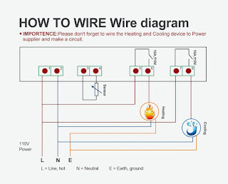
Today I open the instruction manual and am shocked to see the wiring diagram showing the power supply is 12V, not 110Vac as shown on Amazon's product page.
this clearly says 12V and is the model I ordered
this diagram alone is ambiguous as one can interpret the load is also 12V
this verbiage and depictions clearly shows the power supply is 110Vac 50 or 60 Hz
So now I need to set out to find the facts, by testing it to determine if it is 12Vdc or 110Vac. My hunch is it is likely 110Vac but they are just too cheap to reprint the hardcopy manual. It is possible it does not care if you provide it with 12Vdc or 110Vac. If so it would not care if you provide it with 12Vac also.
The other thing I don't like is how they always shows the wiring diagram that the neutral of the load is connected with that of the power supply for the controller. I also bet it is another stupid documentation as often the assumed manufacturer didn't do the design, but just building the final product according to a design house's design. I know this controller is sold under many different brands.
Update 15 minutes later:
I found some wires and hook it up to an adjustable DC power supply. The only safe way to test this is by starting with the low voltage, which is 12V. The fact the diagram does not show polarity nor says AC or DC is a giveaway it does not care.
The main reason I ordered the 110Vac version is someone reported the circa 50mA of quiescent current it consumes - likely mostly for the LED 7-segment displays. It turns out if you switch it off, I draws only a few mA.
consumes 4mA when switched off
consumes 55mA when switched on
I used 12.6V to test
I first found it odd they encased the NTC thermistor with silicone rubber (condom); I think because people have been using this to build home made sous-vide 😆
A few interesting observation. While this controller has a relay for cool and one for heat, they are not indecently settable. They are coupled and set by only one set point. The parameters that I can control are far less than I expected. Only the the target temperature, switching spread in 1 degree C or 3 degree F increments, and the compressor lockout delay of 1 to 10 minutes. I am sure the published 3 degree F spread is really 1 degree C in real computation of the controller algorithm.
It turns out the circa 50mA power consumption is mainly due to one of the two relays being energized. When both relays are off, it draws around 15 - 20 mA depends on how many display segments are on. So the relays each draws about 30mA but they never on simultaneously.
I am going to wire it up to the Coleman AC to test out how well it work. I want to be able to set the temperature just being comfortable but not AC on cold in most of the time.
Modern living made batter through the joys of low cost Chinese made electronics.


No comments:
Post a Comment