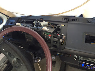
I encountered a setback yesterday afternoon.
I made significant progress in wiring up the charging systems from both the Westfalia battery charger as well as the Vanagon's alternator for seamless handling of both the house and the starting battery banks. At this point I have not commit the installation in case there is a problem. I wanted to check out the Westfalia's battery isolation/combining relay to ensure it is adequate for handing two house batteries. I started the engine and proceed to check the voltages at the relay contacts. To my surprise the relay did not close to bridge the two battery banks together when the engine is running.
At the moment I could not remember how this isolation/combining relay function. Consulting the Bentley service manual offered little help. I did note that the relay coil was not energized.
What could it be? Did I damage something in the electrical system update? Immediately I checked all the fuses in the Vanagon main fuse panel. I could not find any burnt fuse. It was late for me to pursue further. I buttoned up the Vanagon and call it a day.
Back in the house I pour over the Bentley manual's electrical diagrams. Of course there is no description of how this work. I was persistent in carefully study the schematics that spread over different sections (due to this feature is only in Westfalia campers but ties to the Vanagon circuit).
Soon I realized the ingenious design of the isolation/combining relay take advantage of the D+ signal of the alternator circuit. The relay contacts only close when the engine is running, but not during the starter cranking. The D+ signal is the field windings of the alternator. This field winding signals goes to the instrument cluster which house the alternator warning lamp. In addition to the warning lamp, there are two resistors that are in parallel with the warning lamp, and all three components completes the field winding circuit to ground.
During this electrical system update I deliberately left the instrument cluster out (to save the unnecessary wear and tear of the fragile flex circuit) as many wires are routed behind it. I even had driven Isolde short distance around the blocks without the instrument cluster installed. Unknown to me the alternator has not been functioning because of it.
There is only one way to verify my diagnose - to use up one of the remaining 8 lives of the instrument cluster flex circuit by connecting it. I started the engine and all is well. The alternator output was charging both banks of batteries. I wanted to monitor the charge current flowing through the isolation/combining relay to the house battery bank. The 100A shunt of the V/A meter make this really easy to do with a DMM set to mV scale. While the batteries was not deeply discharged I am not monitoring of the worst case charge current. My estimation is at worst it may be near the 30A limit of the relay and the wire in the current track.
the instrument cluster reconnected
problem solved - the Bosch 90A alternator is charging both battery banks
I scrounged enough fasteners from my parts bin to install the battery charger
doing a final check of the charge voltage (and adjusted it) before commit to the final mounting
I had to remove the cabinet partition to fasten the charger
the detachable terminal block is perfect for this
this also allow me to secure the terminal block to the panel using 2 screws
once I am satisfied the charger's output voltage is properly adjusted as well as charging both battery banks I finished the installation and tidied up the wiring; note that the charger fits nicely in this dead space inside the cabinet
i utilize the thick wire from the starting battery to splice in the battery charger and protect it with a 20A fuse; this save me having to run a dedicated wire to the starting battery under the passenger seat
i used three layers of heat shrink insulation after making the soldered splice connection
it took a while to witness the charger switched to starting battery charging priority when the voltage drops below 12.3V
I eventually was able to use this Hella 6 position fuse box that I ordered long ago for this project; I would prefer have it uses screw terminal connection instead of spade lugs - but the price is right for this
it is very important all the hot side wires connecting to the batter bank is fused - as close to the battery as possible
Since the blue LED that indicates the propane burner status of the old 3-way fridge is now defunct, I ponder how best to repurpose it. I could use it to indicate when AC is present and the battery charger is active. However I decided that the V/A meter give me a good indication when the house batteries are being charge. In the end I want to keep it simple - to retain the former association with the refrigerator. Since I implemented a master power switch for the fridge this indicator is very useful for a visual check that the fridge is switched on.
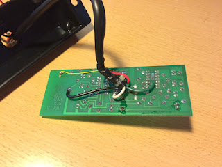
to make this work I have to once again hack the status panel PCB
Very long ago, when I installed my first auxiliary battery in the driver seat pedestal, I hacked the Westfalia LED status panel to allow the monitoring of either battery bank. It is a relatively easy modification which involves a trace cut of the PCB and bringing in an additional B+ from the aux battery. Instead of the original ON/OFF function the SPDT toggle switch became the battery bank select. Of course, with this simple modification, the status panel is always powered and drains a small amount of current continuously. It is a design tradeoff decision not for those constantly troubled by small parasitic drains.
When the blue LED first became available, I installed one in place of the dim green LED that indicates when the Domestic refrigerator burner is lit. The brighter blue LED make lighting the propane fridge easier, and was a novelty at the time.
the fridge-heater-on LED entails an op amp to amplify the minute current from the thermocouple to to that required by the LED; I have to defeat the amplifier and only use the LED and the current limit resistor
I even utilize the thermocouple signal wire for this repurposing - the black wire with the clear plastic spade lug enclosure; doing this utilize the existing wiring and most important, the mating connector so the status panel can be remove for service
the white wire before the modification
the white wire after the modification is moved to an adjacent node where the current limit resistor is
note the snow flake symbol at the blue LED; I am glad I made this choice to preserve the association with the refrigerator
i also mounted the ignition defeat switch for the Alpine head unit; i chose this location that is immediately under the main power button of the head unit for user friendliness in mind (the close association with the power button); it is also well sheltered from being accidentally bumped


No comments:
Post a Comment