One electrical update that I planned to do a while now is improving the headlight light outputs. Vanagon has one of the most inadequate headlight, especially the late model years with the North America-only rectangle headlights. The low beam output 65W each side, and the high beam power are 90W each side. Additionally the headlights are switched directly by a headlight switch without going through relays. This creates significant voltage drop such that the light bulbs see significantly lower voltage.
I chosen a modest upgrade path which consists of changing the bulbs to higher wattage ones, and adding 2 relays to alleviate the burden on the headlight switch.
While I dread to starting this headlight update project, it is best done now that I have the instrument cluster out to minimize the wear and tears on it as well as the various switches and indicators around it.
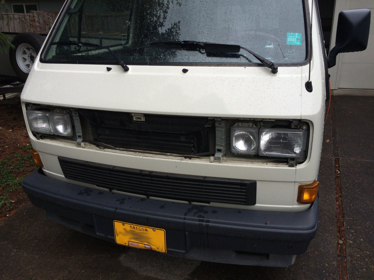
so ugly with the grill removed
the set of new bulbs
new bulb 80W/100W (left) and old bulb 45W/65W (right)
the new H4 bulb for the inner high beams 100W instead of the old bulb at 55W
The new low beam wattage is 100W versus the old one at 65W. The new high beam wattage is 180W versus the old one (two filaments) 100W. A 45% and 80% increase over the old. With the reduction on line and contact loss the brightness should increase about 80 to 100%.
the higher wattage H4 bulb has a metal tab that I had to trim off to fit the light fixture
looks like a blind person
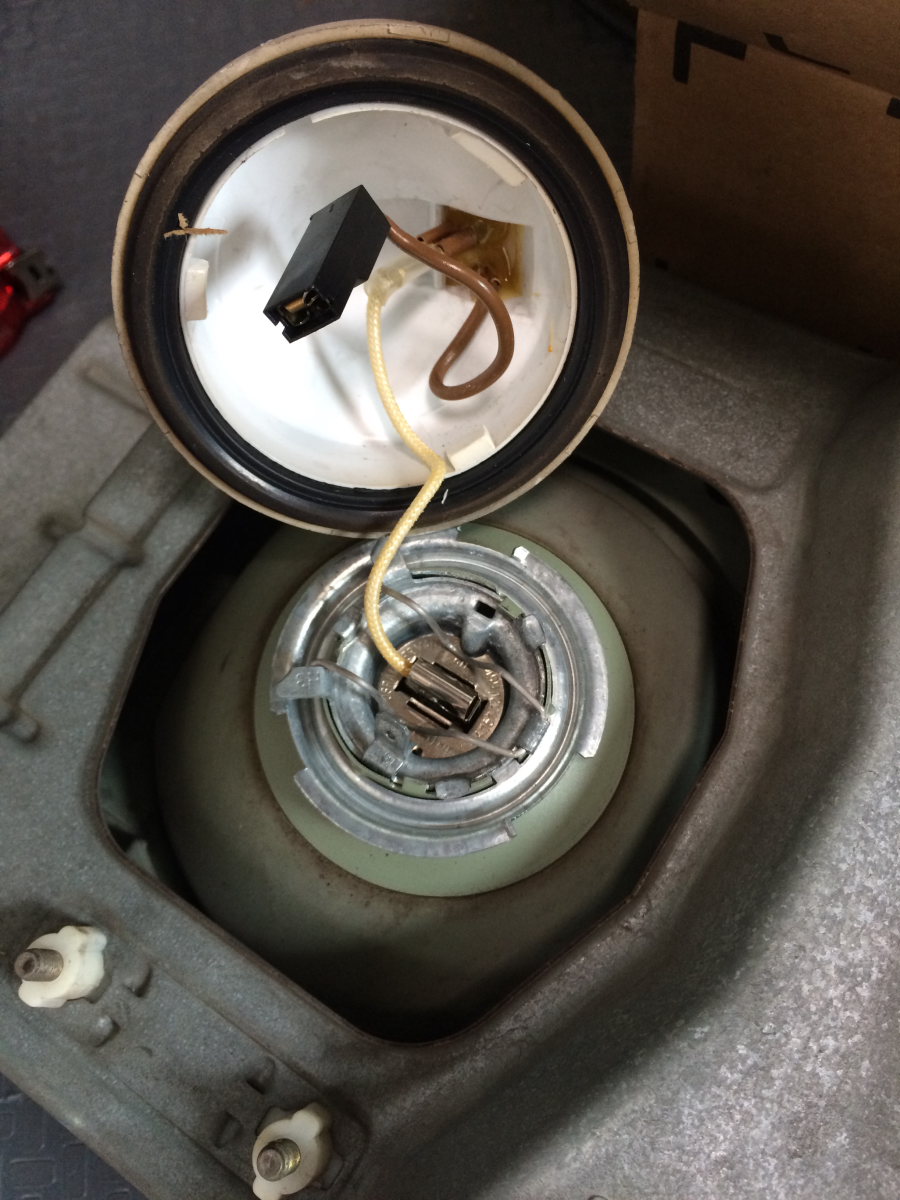
the headlight fixture with new bulbs installed
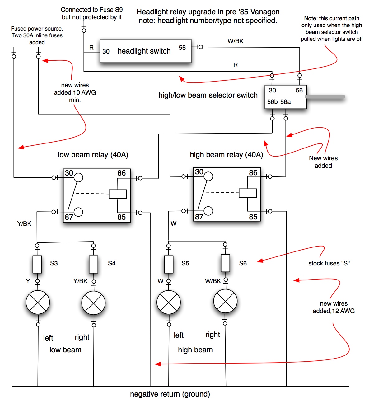
The headlight circuit modification involves adding two 40A automotive relays to allevate the headlamp swtich and the high/low beam switch the load currents from the head lamps. With independent conductors for the +12V supply and the used of relays line loss is significantly reduced.
I use this schematic
generously compiled and shared by a fellow Vanagon owner
VW was nice to provide a few unused spade lugs for unfused B+ power where I can tap in for the relays; before dropping the main fuse/relay panel I disconnected both battery banks; this is a safety procedure not to be taken lightly
it would be nice to increase the gauge of these wires but that will entail too much work for rather marginal improvement
i noted that colors of the wires and they do match up with that in the Bentley service manual; the left an right, high and low beams are all individually fused; all these placed a few constraints to the approach of the modification feasible
I was hoping to be able to compare side by side the before and after difference of brightness by leaving one side new and the other old. However that would be difficult since the constrains don't lend to this configuration. I have no doubt, however that the difference of the update is like day to night comparing to the poorly performance of the factory system.
Back to the other aspect of the update. I plan to fully take advantage of the old refrigerator vent port on the side of the kitchenette for enhance electrical functions. I am awaiting the shipment of the inexpensive USB power port which I want to mount. The main power shutoff switch for the new refrigerator will also be mounted next to it. The power ports will be very handy for using mobile devices in the cabin.
a simple snack to tide the stomach over until sun down
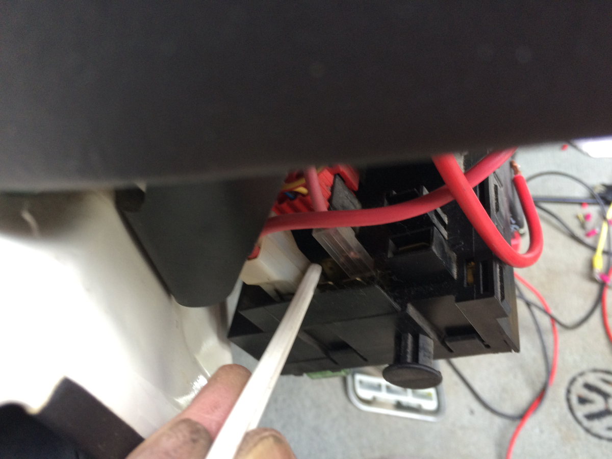
the red wire is the only +12V power supplying the entire light switch which carry the current for all the running lights, license plate light, instrument lights, and both high and low beam for the head lights. It is no bigger than 14 gauge
the red wire leads to one of the thin contact on top of the light switch - amazing!
i have never notice this tiny classic westfalia decal behind the driver seat
I carefully traced the conductor for the high beams - the white one where my index finger at
the conductor for the low beams is the yellow wire; both these wires are cut and a relay added with +12V tapped from the fuse/relay panel
here I am splicing in the relay socket - i make all my connections with soldering, followed with more than one layer of heat shrink tubing or a good wrapping of electrician's tape;
i dislike the compression plastic splice connectors - to me they don't look that reliable (compared to well made twisted and soldered joint) and my biggest reason for dislike is they then to snag on other wires
on the left side above the diver foot well are two ground trees which the relay coils would be grounded to
two 30A fuses are added for the +12V tapped from the fuse/relay panel; one for the high beam relay and one for the low beam relay; the black wire is to be connected to the ground tree
before I button up the instrument cluster I ran this white wire behind it down to the driver foot well to serve as pilot lead in case I need to run additional conductors; this avoid the laborious removal and replacement of the instrument cluster
the head light upgrade is a success; it is so much brighter; feeling like a brand new vehicle; the light is white instead of yellow and it feels like at least "twice as bright"
I went out for a drive and the difference is dramatic - like day to night


No comments:
Post a Comment