
A few months ago I carried out converting Isolde's inefficient refrigerator to one with a 12V compressor. Because of it an increase of energy storage capacity is needed on the house battery. I replaced the rather inadequate single group 41 with 2 deep cycle batteries. This calls for a substantial overhaul of the electrical system.
Finding the best batteries for my needs was no easy task given the constraints and requirements.


interestingly the ones in bulk package tastes better and is clearly different kind of mackerel

One of the major update is the audio system. I removed the head unit, a bridged amplifier for the rear channel speakers, and a CD changer. In their place will just be an Alpine head unit that supports Bluetooth, USB, and auxiliary input in addition to the common functions.
am/fm with cassette head unit with aiNet CD changer control functions

4 channel amplifier configured as 2 channel bridged amplifier

6 disc CD changer with aiNet (all digital) interface

i begun the wiring work for the new Alpine head unit; this time i am adding an ignition override toggle switch; i am still undecided where to drill a hole to mount the switch


a few new wires would be routed behind the cabinets on the driver side; i put a lot of thought into minimizing the number of conductors


i found a piece of aluminum to fabricate a face plate to house electrical functions using the old refrigerator's ventilation port in the cabinet; the tentative functions are power switch for the fridge, 5V USB power ports for mobile devices, or the V/A meter


my hand written documentation from nearly 20 years ago


the existing isolation circuit consists of one single 30A relay


while contemplating the electrical wiring update, i identify the need for an external shut off for the DC refrigerator; it is a very convenient feature to save me from having to shut it off via the temperature control dial during storage; i reuse the rocket switch from Brunnhilde's auxiliary tank project - perfect

i found a piece of aluminum to fabricate a face plate to house electrical functions using the old refrigerator's ventilation port in the cabinet; the tentative functions are power switch for the fridge, 5V USB power ports for mobile devices, or the V/A meter


I have this spare battery charger for Brunnhilde. I decide to install it in Isolde. It is a 10A charger that supports two batter banks. It has temperature compensated charge voltage regulation for the house batter bank. It will give charge priority to the starting battery if it fallen below 12.4V. One challenge is I don't have the mating connectors for it. To overcome this I have to open the charger, remove the connectors, and solder in wires so that I can add an external terminal block.


I have this terminal block that I collected long time ago and how it will fulfill its purpose. It is very high quality and you can separate the two halves like a connector pair. It is perfect for what I need. Before I begin my hack, I perform a quick check to see if the charger is functional. Well, it turned out it is bad. There is no voltage on any of the outputs.
I figure it is likely it blown an internal fuse. My guess is the original owner of Brunnhilde had tried to use it in Europe and the 220V supply damaged the charger. The reason of my guess is Brunnhilde now has a worldwide (115/220V 50/60Hz) version of this same charger. I open the charger and found the main fuse (a 3.25A slow blow mini fuse) is indeed blown. The fuse is soldered down but that did not stop me. After replacing the blow fuse there are voltages at all the outputs and sense lines. I knew I have to be cautiously careful as the charger may have other defects. I would have to conduct a full function tests before installing it into Isolde.
i proceeded with my terminal block modification


The charger support an optional NTC thermistor. Since I don't have one handy I have to forgo this function for now. Strangely the charger's output voltage seems quite high. Reading the manual carefully I realized that I need to substitute the NTC thermistor with a 500 ohm resistor if I don't have one. Sure enough the voltage is lower to the reasonable range (there is a trim pot for this adjustment) after I added a 520 ohm resistor.


here is a link to a product selection guide for NTC thermistors from Vishay
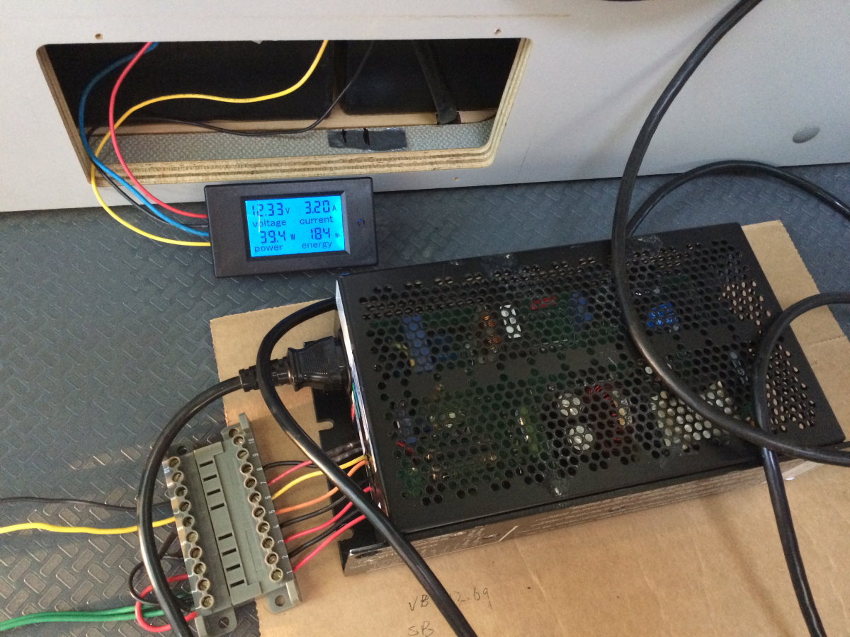
I found this cheap V/A digital meter on Amazon. The information provided is minimal. One have to choose between a 20A or a 100A model. The 20A one is a no go because of the charge current by the alternator will greatly exceeds its internal shunt. The only choice is the 100A model. I was concern with its accuracy for current range of a few tens to a few A. I decided to order it and only use it if it pass my inspections.

Because of the design of the meter, it can only measure the current one way. Obvious the choice is the current being consumed by the load. What happen when the current flow in the opposite direction. This will drives the sense voltage below ground (negative). I have to hope the meter is designed to handle this (typical with a clamping diode at the sense input to protect the electronics from being damaged). This is a test that I carried out right away. All is well. The meter just shows 0 current when the current flow is into the battery bank.
Next tests are the accuracy tests for the voltage and current measurements. My biggest concern is current measurement accuracy with the typical sustained power consumptions - ranges from 10s of mA to less than 10A. Compared to my DMMs the voltage is within 10mV. Very good but is expected with today's electronics. The most likely weak link with the current measurement is the accuracy of the 100A shunt.
To my pleasant surprise the current measurement is very accurate, comparing to my Fluke DMM checked with mV measurement across the 100A shunt. It is definitely good enough for the purpose of keeping tack of how many watt hours of energy consumed since charged.

tentatively I am thinking of mounting the V/A meter at this opening left over from the decommissioning of the heater under the bench seat; however one draw back is at this level the meter cannot be read at normal eye level unless it is tilled up slightly


No comments:
Post a Comment