
This resumes from a previous post in good shape, isolde - part 9.
Isolde's digital clock on the instrument cluster begun to develop a gradual failure on the LCD display a few years after new. Over the years the tumor-like grew steadily increased until the clock display became unusable.
New replacement part had dried out decades ago. I have been keeping my eye out for finding a used replacement, thought it have not been a high priority for me. Last week I thought I would just add to my signature area at a Volkswagon users forum that I am looking for this clock. I was not optimistic that anything would come of it.

I was so wrong. Within the same day I received 2 private mails. The first pointed me to one for sale on eBay. A few hours later, the second one came in with the user telling me that if I just provide my address he will ship me one that he has, without asking for any compensation!
Today the package arrive, and I was delighted. I have been deferring putting Isolde's dashboard and many trim pieces back together because I want to get the clock replaced so I don't have to tear the dash apart again.

the LCD clock the generous Vanagonaut shipped me

I pulled out the instrument cluster; I wanted to determine the polarity of the electrical connection of the clock so I could test its functionality before installing onto the instrument cluster

Evidently the flexible circuit foil in the Vanagon instrument cluster is susceptible to failure due to age so I am extremely nervous in handling it. Removing the light bulb was a bit tricky. While I found the instruction that it requires a 90-degree turn to remove, it was very tight. With the parts this old it is better safe than sorry. Once I was quite sure about the right removal method I turn it hard and were able to remove the light bulb. The next step was no less concerning. I had to ply the circuit flex print to disconnect the clock's 2-pin connector.


with the aid of two mil-spec connector contact pins I was able to securely make the electrical connector to perform the tests

When I connected the good clock, I was disappointed the leading minute's digit appeared to be bad. I then thought may be it is due to the bouncy of the electrical contact from how power was applied to it. I used a toothpick to roll over the minute digits, and sure enough 0 through 6 all displayed correctly.
all the digits checked out good
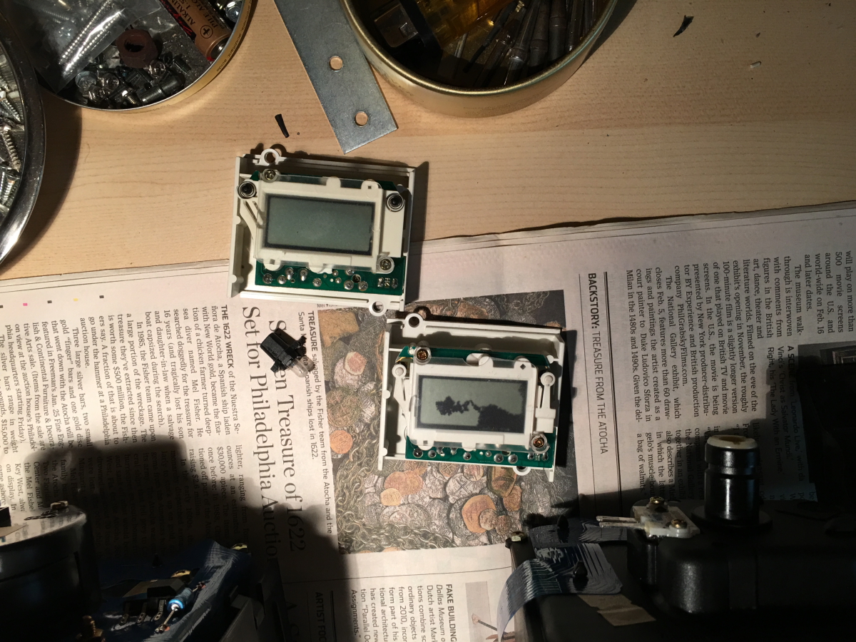
the two clocks are a little bit different; I think mine bad one has a later manufacturing date


I tried to give the good clock a bit of cleaning before assembling into the instrument cluster, but cannot remove a persistent finger print smudge. I swapped the transparent faceplates.

here is the backside of the clock PCB inside - note the trimmer capacitor that is a part of the crystal oscillator circuit that one can adjust the clock speed if necessary; note also the light pipes that direct the light from the bulb to two ends of the LCD display


the good clock is now pristine looking; note the access hole on the PCB to adjust the speed to be the accuracy of atomic clock

Once I was satisfied with the functional checkout, I proceed to install the good clock into the instrument cluster.
again upon power up the first time the leading minutes digit is garbled so it is normal

I am so happy that after all these years Isolde again have a good working clock

I carefully reassembled all the trims of the dash, replace the glovebox, and the audio head unit's trim as well

now Isolde's dash console once again looking shipshape

here you can see the new cup holder mounting track looks so much better than when some of the dash trims were not installed


photos credit dannydanny in the above link
Curiosity gotten a hold of me so I took apart the bad clock to check. Here are the photos of my bad clock.
the clock chip reside under the LCD display; the LCD electrical connections to the PCB are made via two elastomeric connectors (the two pieces of black rubber-like strips, one still stuck to the LCD contact fingers and the other stuck to the other connection row on the PCB)


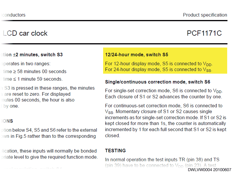
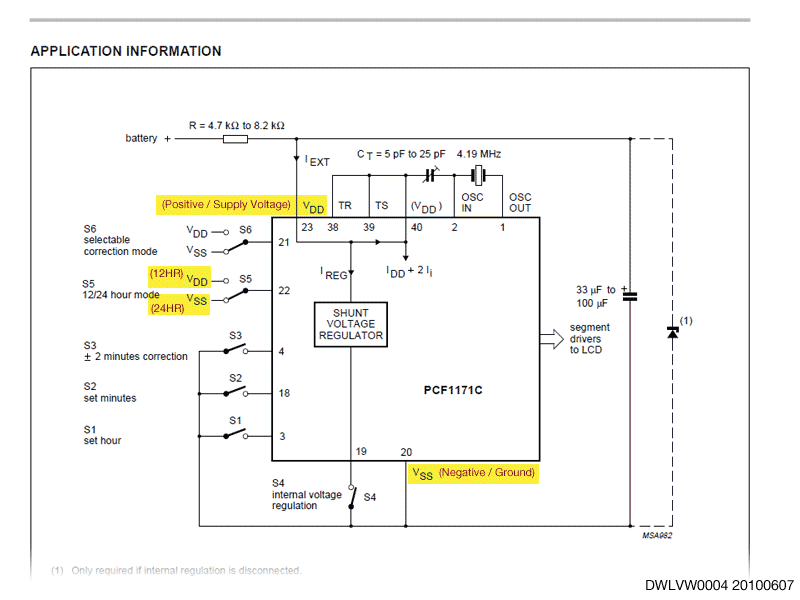
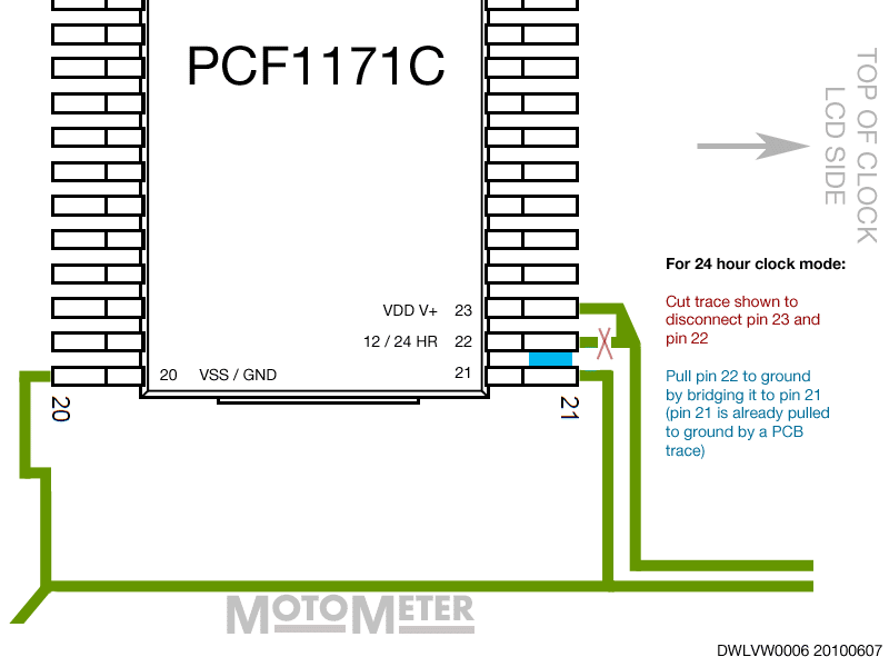
The IC package is different from the one dannydanny dissected. While I cannot see the part marking because of the epoxy, I infer it is very likely the same Philips PCF1171C, just in a different packaging. While I would prefer to do the hack to set the clock mode to 24 hours display, it is not something I am willing to risk because it entail disturbing the fragile LCD display.
I did a quick check online try to download the datasheet. However I found none that I feel comfortable to for the fear of contracting malware. Searching NXP's site yields no hit as the part is long obsoleted.
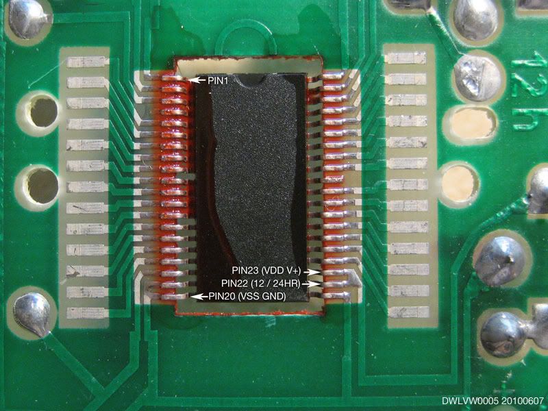
I spent just a minute or so to attempt to determine the pin-1 position, and hence the relevant pins for setting 12/24 hour formats. There is no ready indication which is pin-1, but I have little doubt I can figure out by spending more time tracing the circuit board traces. What is very interesting is the many punched holes on the PCB functions to configure the final circuitry. The holes punches out the PCB at the predetermined location to sever the traces. What is most surprising is the total number of traces that are severed.

No comments:
Post a Comment