
This is the continuation of a series of post staring with my purchase of an Arduino Uno microcontroller board. Started as a project in search of a mission soon it took on an evolution. It evolved into a project that fulfills some needs that I have long wanted to address and more.
Initially I just wanted to create a digital display for the engine oil temperature and pressure of the Westfalia Vanagon camper (Isolde). Soon I wanted more functionalities. I chose a data logger to be a part of the functions.
Here is the link to the previous posts of this evolution and design and development:
invested in a microcontroller board - part 1
invested in a microcontroller board - part 2
invested in a microcontroller board - part 3
a multi-function display for isolde - part 1
a multi-function display for isolde - part 2
a multi-function display for isolde - part 3
a multi-function display for isolde - part 4
a multi-function display for isolde - part 5
a multi-function display for isolde - part 6
a multi-function display for isolde - part 7
a multi-function display for isolde - part 8
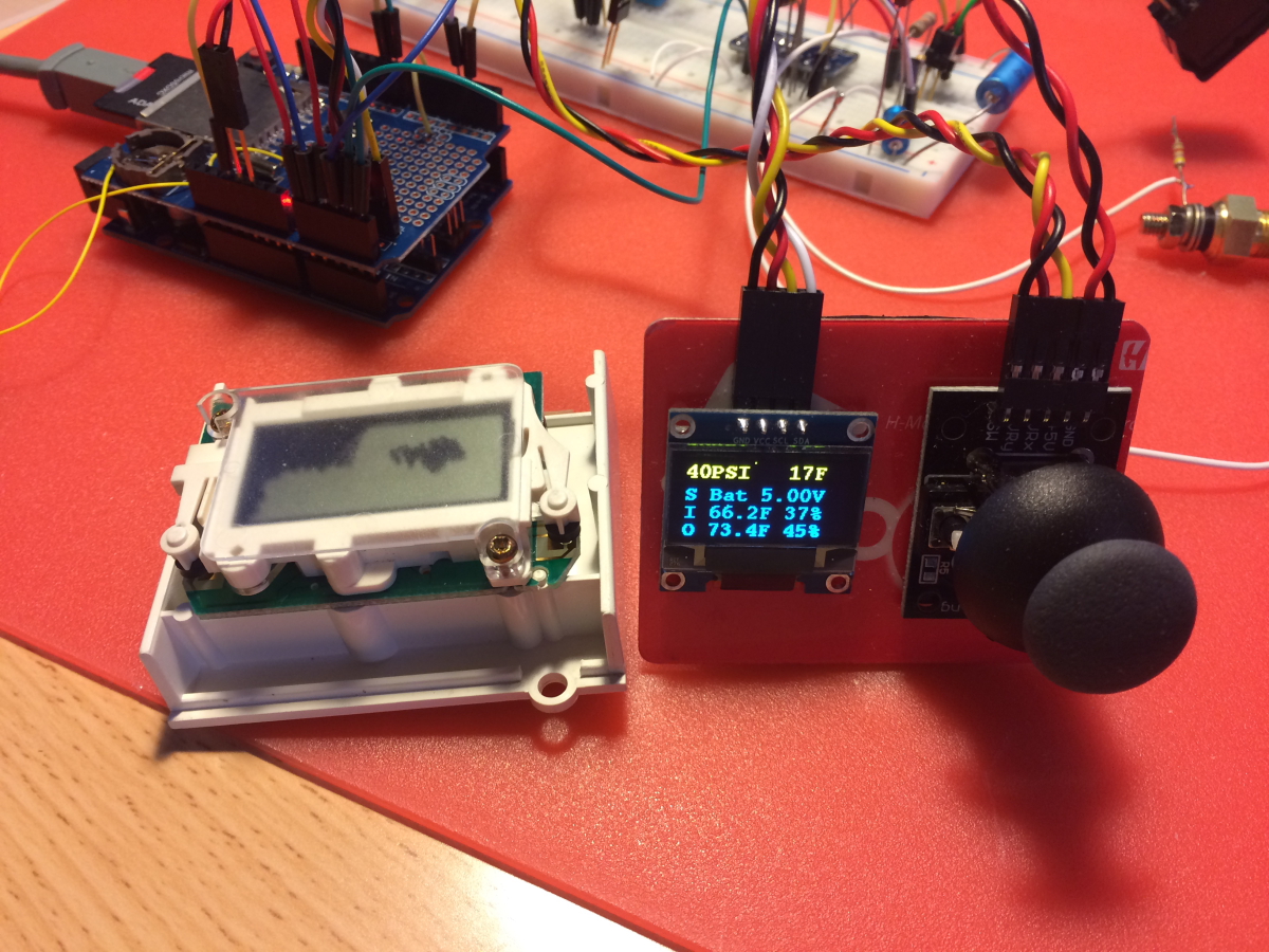
With the most difficult parts of the software out of the way, I devoted some more thought to the packaging of the three modules - the microcontroller module, the joystick HID (human interface device), and the OLED display. I want to mount the joystick and the OLED in locations that are ergonomic. I chose the accessory track that I designed to support cup holders. I planned to mount the microcontroller module somewhere else that is not so prominent.
For DIYs of electronic instrument one of the most challenging part of the projects is to package it to achieve a professional look and feel. This effort can easily be more costly in time and monetarily. The advent of 3D printing enable DIYs to create one-off custom enclosure. I don't have a 3D printer so I have to try harder.
I have not been giving much attention to the packaging of the OLED display and the joystick. I only have a vague notion that they both would be mounted onto the accessory track in Isolde. Now that the software has taken shape and I am quite confident of the execution I am devoting more thought as to how to achieve an acceptable packaging for the OLED display. My new thinking is to replace the Vanagon's LCD clock with this OLED display. It is a shock for me as I did not want to mess with the Vanagon instrument cluster. However as I struggle with how to enclose the OLED display I am leaning towards placing it in the location of the factory LCD clock. Since the software is becoming quite shipshape and I am not against the wall of running out of memory I can add a few line of code and an optional clock display page. Therefore maintaining the clock function at this location.
While I try my best to maintain the factory integrity of the original Vanagon aesthetics there is a boundary of compromise that I am willing to cross to maintain harmony. Since the Arduino based multi-function display and data logger is well capable of fulfilling the factory LCD clock function it is good enough reason to displace the factory clock with my OLED display. Doing so will avoid creating a display ghetto on the accessory track. The only addition to the accessory track would just be the joystick. The more I think about this, the more I like the idea. The only visible part of the multi-function display of this Arduino-based system would just the joystick which would be mounted onto the accessory track. It would just be the most minimal footprint.
The advantage of partitioning the system into 3 modules - the processor module, the OLED display, and the joystick module. It allows for a significant modifications of the processor module without affecting the other two modules! For example, should a more attractive Arduino data logger shield come about in a later day, I can swap it into the processor module and update the software to work with it. Another example is should I decided to change the I2C ADS1115 4 channel ADC with something else, I can do the swap without having to touch the OLED display or the joystick.
The plastic filter of the Vanagon clock module is 30.74mm high x 42.6mm wide. The OLED dot matrix display active area is 27.38mm wide x 27.90mm high. I should be able to fit the OLED into the Vanagon clock module.
the Vanagon clock module with a deteriorated LCD display

this clear filter would be reused

the display plastic frame with integral time setting buttoms

the clock LCD display compared to the OLED display
the OLED is thicker and there are discrete components on the back side of the display


it would be a challenge to shoehorn the OLED into this clock module to achieve a factory look

I modified the plastic face frame to accommodate the OLED assembly

Securing the OLED module and aligning it square and center in the original LCD aperture would be most challeging. It is very easy to mess this up. I chose to keep the PCB for two reasons. I use it to secure the OLED module. By keeping it I can preserve the two time setting push button switches and add them to the Arduino multi-function display system. The two push button are constructed out copper etching on the PCB. When pressed, the elastomeric rubber grommet mounted on the display face frame shorts out the PCB etchings and close the switch. The resistance of the elastomeric rubber grommet is quite high, measuring a nominal 1k ohm. I reckon they are compatible with the AtMega328 digital input pins' built in programmable pullup.

there are 6 wires - Vcc, GND, SDA, SCL, and the two push buttons of the Vanagon clock module

I tested the high impedance switches of the clock module and they work

My choosing to mount the OLED into the clock module is a coup. I gained two switches and not having to fabricate an enclosure and to find a mounting location for them. One of them will be wire to the reset signal of the Uno. Being able to reset the uC with a paperclip on Vanagon clock. I cannot plan it better than this. Despite its high resistance, it barely can overcome the pullup resistor on the reset signal. I tested it and it works.
To make the OLED look factory, I would need to mask off the surround of the clear plastic lens.
Hi - I love what you are doing. I have an '84 Westfalia Joker and have been thinking of doing something similar. Have you taken a look at the mpguino project? Gives a live reading of mpg based on signals from the injectors and speed sensor. It would be a great feature to have. Are you still developing yours?
ReplyDeleteThanks for your comment and interest. I am not aware of the mpguino project until now. My design goals and requirements are quite different and as they are already taxed the resource of the uC and size that I aim to achieve. With projects like this doing the prototype and coding are the easy part. The most difficult is how to achieve a satisfactory final appearance, functionality in keeping with the factory instruments and aesthetics. There are vast number of conductors to be addressed and the packaging of the modules prove to be very challenging. The biggest challenges are achieving the clean wiring that is safe and serviceable and have the modules do not look like a hack job. I have not abandon the project, just put it on the back burner as I have too many other interests.
ReplyDelete